How do you wire the ignition signal on a DC charger?
6 min read
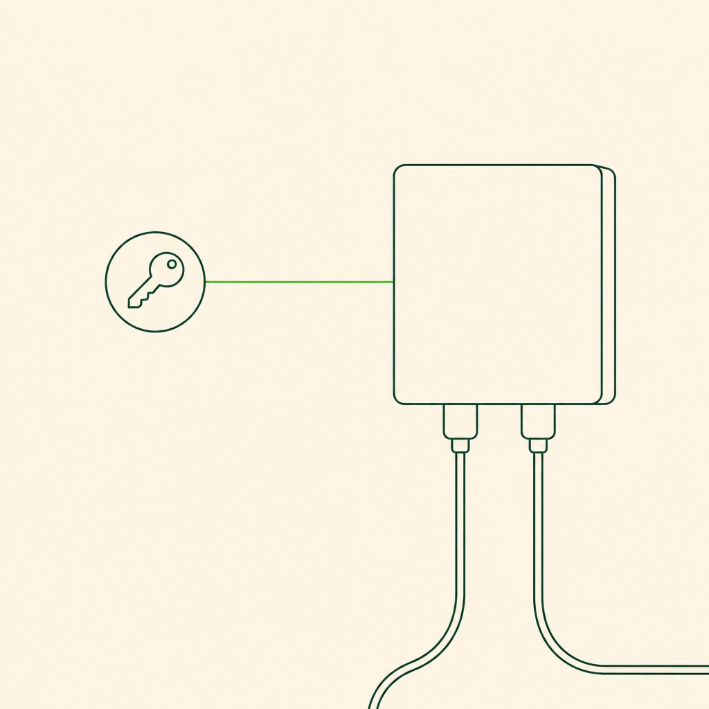
It is a small signal wire from an ignition-switched source to the charger's control input, and it exists so that the charger only charges with the engine running. The DD range publishes an external remote switch control for charging; the wire in that circuit carries almost no current, so it is a signal rather than a supply. The failure to avoid is feeding it from a permanently live circuit, which leaves the charger free to run whenever the input has voltage.
What the signal is for
A DC charger connected straight to the vehicle's electrical system would happily discharge the starter battery into the leisure bank when the engine is off, because from the charger's point of view a live input is a live input. The control input is what distinguishes a running engine from a parked vehicle, and the DD range publishes it as an external remote switch control for charging rather than an automatic engine sensor.
Where to take it from
- From an ignition-switched circuit that goes live with the key or with the engine running, which is the behaviour the charger needs.
- Not from a permanently live circuit, and not from the thick charge cable: the control input is a signal and pairing it with the main feed defeats its purpose.
- Through its own small fuse if it is tapped from a vehicle circuit, so a fault in the signal wire cannot take a vehicle system down with it.
- With the vehicle's own quirks in mind: a circuit that stays live for minutes after the key is removed is acceptable, while one that is live on accessory alone may let the charger work with the engine off.
Testing it
- Measure the control input with the key removed: it should be dead. If it is live, the charger is allowed to run when it should not be.
- Measure it again with the engine running: it should be live. An intermittent tap here looks exactly like an intermittent charger.
- Watch the input voltage at the same time, because the two together tell you whether the charger is being asked to work and whether it has anything to work with. On the 12V 20A to 60A range the published cut-off is 8V with restart at 10V.
- If the charger has an app, cross-check the control state against the readings instead of trusting the wire by itself.
The shortcut that causes most of the trouble
Bridging the control input to the main positive cable is the fastest way to make a DC charger work in a driveway test, and the fastest way to flatten a leisure bank in a lay-by. If the charger on your van charges with the engine off, that bridge is the first thing to look for, and it is also the first thing to remove before you diagnose anything else.
Frequently asked questions
- Can I wire the DC charger without an ignition signal?
- The charger will work, and it will also be able to run with the engine off. The DD range publishes an external remote switch control for charging precisely so that the installation decides when charging is allowed, so wiring it permanently live removes the protection rather than simplifying the job.
- Which wire should I tap for the ignition signal?
- A circuit that is live with the engine running and dead with the key out. Small accessory circuits fit that description better than anything carrying a large load, and the control input draws almost nothing, so a thin wire and its own small fuse are appropriate.
- Does the control wire need a fuse?
- If it is tapped from a vehicle circuit, yes. It carries almost no current, but a short in the signal wire should blow its own fuse rather than damage the circuit it is tapped from.
- My charger charges with the engine off. Is that a fault?
- It is usually a wiring decision rather than a failure inside the unit, and the control input is where to look. A charger with a permanently live control input behaves exactly like this, and bridging the control to the main positive is the usual cause.