What should you check before crimping an MC4 connector?
7 min read
MC4 is a family of connectors rather than a single part, and two connectors that look identical can come from different families that do not seal or latch against each other. Four things decide whether the joint survives: the connector has to be rated above the string's short-circuit current rather than its operating current, the crimp has to be made with the die that matches the contact and the cable, the two halves have to be the same family so the seal actually closes, and the pair has to be latched and then pulled to prove it. A connector that is not latched, or was closed with the wrong die, becomes a high-resistance joint in a place nobody inspects.
What the connector is doing
A solar connector has two jobs and they are independent. Electrically it has to make a gas-tight metal contact with low resistance, because it sits in series with the array and any resistance there is a small heater running all day. Mechanically it has to keep water out and stay latched, because it lives outdoors for years and nobody looks at it again after installation.
Both jobs are done by the mating of two specific halves. The seal is formed where one housing enters the other, and the latch is a pair of clips that only engage if the geometry matches. That is why the family matters more than the brand name printed on the housing.
Size it on the short-circuit current
The current to compare against the connector's rating is the short-circuit current of the string, not the current the panels deliver while working. A panel's short-circuit figure is always the larger of the two, and it is the number the connector has to survive rather than carry.
| Panel in this range | Isc | Imp |
|---|---|---|
| 50W | 3.1 A | 2.8 A |
| 100W | 6 A | 5.5 A |
| 130W | 8.1 A | 7.4 A |
| 150W | 9.1 A | 8.3 A |
| 170W | 9.1 A | 8.3 A |
| 200W | 12 A | 11.0 A |
| 230W | 12 A | 11.0 A |
The crimp is half the connector
- Use the die that matches both the contact and the cable size. The same tool with the wrong die produces a joint that looks closed and is not welded.
- Push the contact into the housing until it clicks. On most families the metal contact is retained by a small latch inside the plastic, and a contact that has not clicked can back out when the connector is unmated.
- Pull on the cable, not the housing. The contact should not move inside the housing.
- Check the seal is present before assembly. It is a separate ring on many families and it is easy to lose on a roof.
Do not mix families
Two connectors from different families will often push together and hold. That is the problem: they hold by friction rather than by the intended latch, the seal does not form where it was designed to, and the contact pressure is whatever the two mouldings happen to produce. The joint works when it is made and degrades quietly afterwards.
If a string has to be joined to an existing connector, use a mating half from the same family as the one already there, or replace both halves as a pair. Keeping one spare pair of the family you standardised on is cheaper than diagnosing this later.
Keep the voltage under the controller's limit
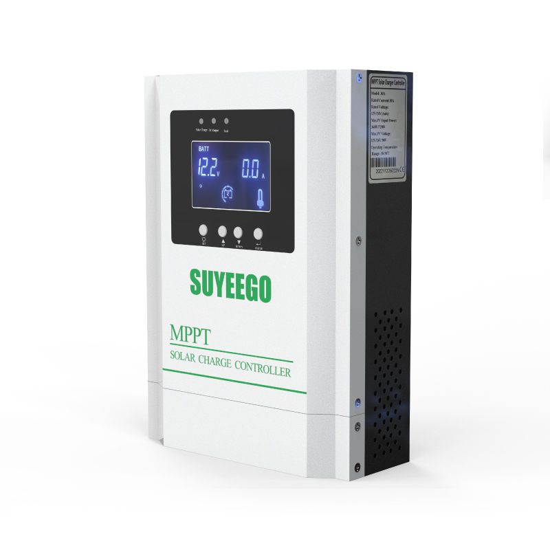
Connectors are not usually what limits string voltage, but the string they terminate is. Open-circuit voltage adds for every panel in series, and it rises further in cold weather. The controllers in this range publish their limit: 80V for the 20A model on a 12 to 24V battery, 105V for the 30A, 130V for the 40A, 60A, 80A and 100A models, and 180V or 280V on the higher battery voltages.
Work the sum with the panel's Voc rather than its Vmp, then add the cold-weather margin. The panels here run from 21.5V to 25.8V open circuit, so four of the 230W panels in series is 103.2V before the temperature correction, which is already past the 80V limit and close to the 105V one.
Where these joints actually fail
- Hanging in the air with the cable's weight on the connector, so the latch takes a load it was never meant to carry.
- Lying in a puddle or at the low point of a run, so water sits on the seal rather than running off it.
- Unmated and left open in the sun, with the contacts exposed to moisture and grit for months.
- Reused after being unmated repeatedly, with the seal hardened and the latch weakened.
- Taped over to hide a joint that was never latched, which keeps the water in as well as out.
The parts this range uses
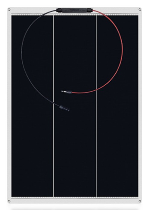
The flexible panels in this range run from 50W to 230W with an open-circuit voltage between 21.5V and 25.8V and a short-circuit current between 3.1A and 12A, which is the range the connectors and the string arithmetic have to cover. The controllers publish a maximum open-circuit voltage of 80V to 130V on 12 to 24V batteries depending on the model, so the panel count per string is decided by the controller rather than by the roof.
Frequently asked questions
- Can I join two different brands of MC4 connector?
- They will often push together and hold, and that is the trap. The latch and the seal are designed as a pair within one family, so a mixed joint holds by friction and does not seal where it was meant to. Use the same family, or replace both halves.
- Should connectors be rated for the panel current or the string current?
- For the string's short-circuit current. In a series string that equals one panel's Isc however many panels there are; in parallel the Isc values add. Use the short-circuit figure rather than the working current, because it is the larger of the two.
- How many panels can go in series on one controller?
- As many as keep the string's open-circuit voltage, corrected for cold weather, below the controller's published maximum. The limits in this range are 80V to 130V on 12 to 24V batteries depending on model, and higher on 48V and 96V systems.
- Why do solar connectors get warm?
- A warm connector is a resistance, and the usual causes are a crimp made with the wrong die, a contact that never clicked into its housing, or two halves from different families pressed together. Compare it with its neighbours under the same sun; the odd one out is the one to remake.